Before new route generationselect your field, fill in vehicle settings and select the proper implement for operation.
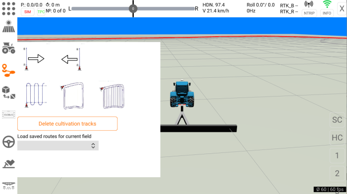
Several route patterns are available in the Tractor Pilot app. To select the pattern click "Navigation" icon at the left sidebar.
Straight AB Line
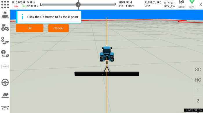
To create the AB Line to follow click one of the AB icons. The icon arrow is pointing the direction of headland U-turn. If you plan to make a right (clockwise) headland U-turn at the end of AB-line select the icon with right arrow. For left U-turn select the icon with left arrow. After icon click the orange reference line will appear. Allign your vehicle to the required AB-line direction and click "OK" button to fix B point and finish the AB Line creation.
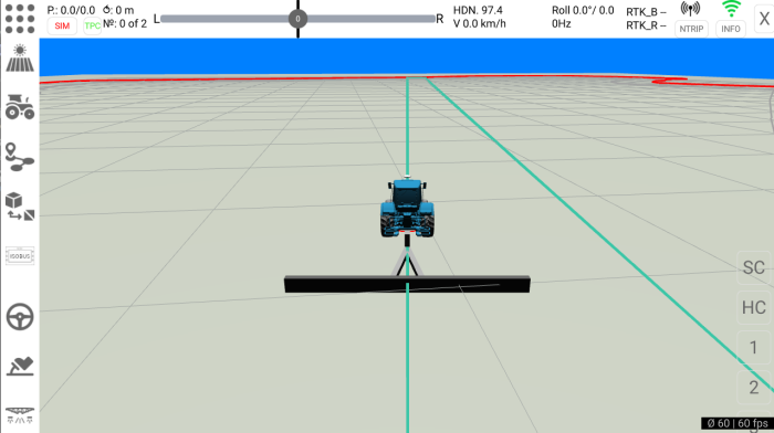
After "OK" button click a new AB-line will be created.
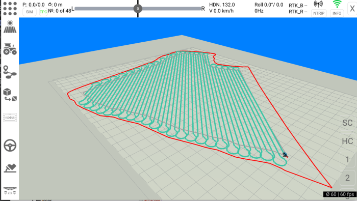
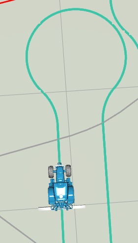
The U-turn will be generated at the end of the line. U-turn type depends on the implement working width. If the implement working width is less then twice tractor min. turning radius then the Ω-turn (keyhole/bulb turn) is generated:
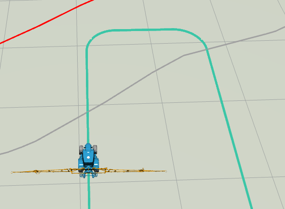
Otherwise the U-Turn is generated:
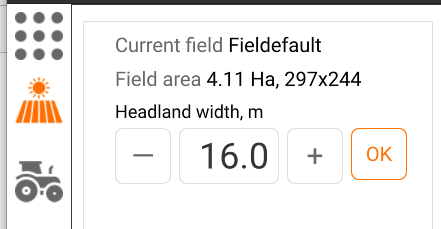
By default the headland width is calculated as a triple minimum turning radius of the tractor. If the implement working width is greater then this value then the headland width equals implement working width. The headland width is recalculated each time you change the implement. If you want to change the autocalculated width value click "Field" icon at the left sidebar and fill-in a new value in the respectful field.
The headland borders are visualized as dark grey lines.
When you reach the end of the AB Line the next line will be generated automatically
Parallel lines
Parallel lines with U-Turns at the headland is the most common field driving pattern.
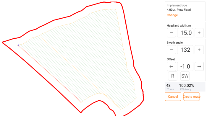
Active implement and its working width is shown under "Implement type" section. Click "Change" if you want to select an other implement. Correct the headland width if necessary (the default headland widths is explained in the "Straight AB Line" chapter).
The swath angle should be adjusted to achieve the minimum number of headland U-turns. Change offset value if you need to move all the batch of lines.
The starting swath is colored red. Click "R" button to swap first and last swath. The blue square represents the route starting point. To move the starting point to the opposite side of line click "SW" button.
Click "Create route" button to generate the field route.
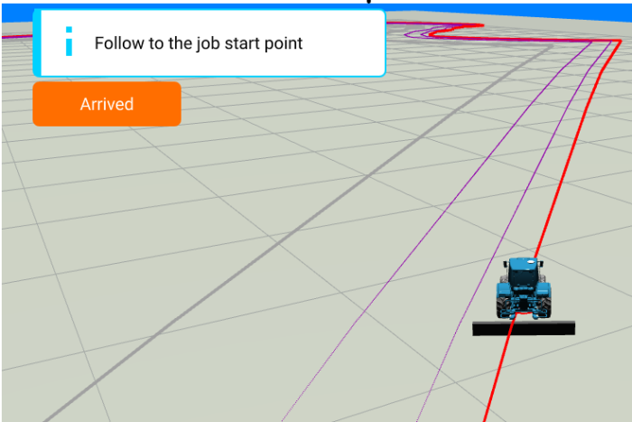
Follow the starting point and after you arrive there click Steering Wheel icon to engage autopilot.
Headland
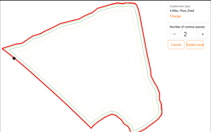
Select this navigation pattern if you need to drive one or more times around the headland.
You can define the route start point by clicking at any part of the red field border - black square representing the start point will appear. If you don't define the start point at this step it will be set automatically after you click "Arrived" button.
Enter the number of headland passes and click "Create route" button.
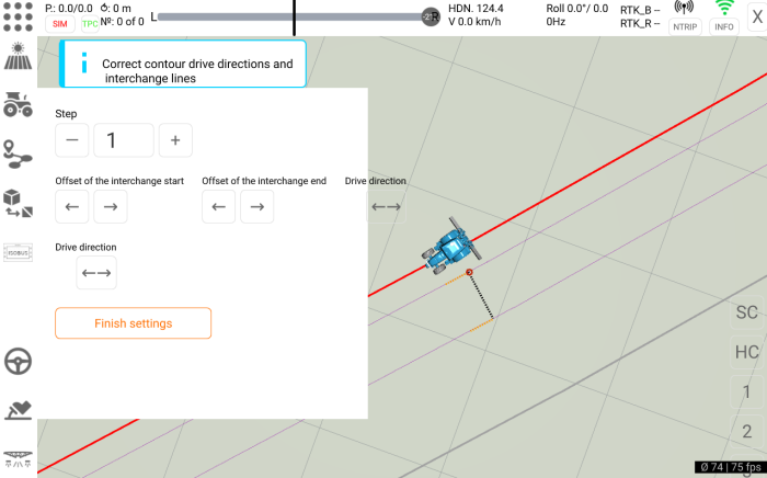
Yellow lines represent drive direction on the headland pass. Click Drive direction buttons to swap directions. Black lines are the connectors between headland passes. You can move connector end and start points with step defined in Step field by clicking Offset of the interchange start/end buttons.
Click "Finish settings" button after you finish corrections.
