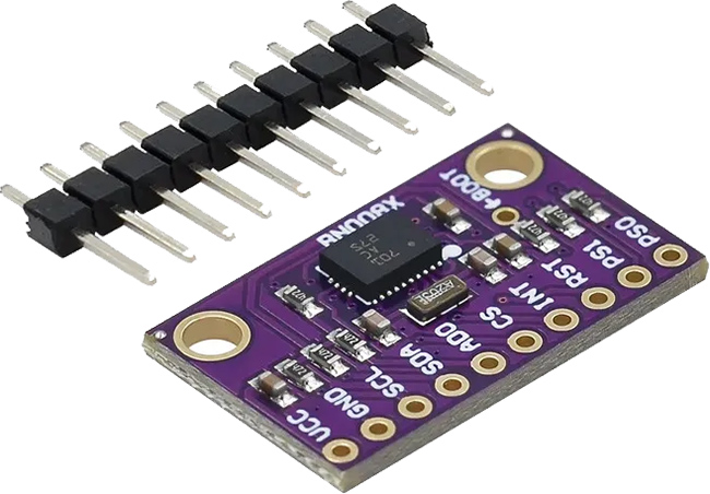
Heading and roll angles are determined either by dual gps or by fusing data from single GPS and IMU (Inertial measurement unit). If you use single GPS installation you'll need BNO 085 IMU sensor. Check this forum topicto find out where this module can be bought from.
The BNO 085 IMU can operate in 2 major modes - regular mode over i2c interface and RVC mode over UART. Both modes are supported in TP software.
Wiring

For regular mode connect the IMU to the I2C interface of the Raspberry Pi computer. By default i2c-3 interface with SDA line on GPIO18 pin and SCL line on GPIO 19 is used. So the connection diagram is as follows:
BNO 085 SDA - RPi SDA-3 (GPIO 18)
BNO 085 SCL - RPi SCL-3 (GPIO 19)
BNO 085 VCC - 3v3 Power
BNO 085 GND - any Ground pin
For RVC mode connect the IMU to theUART-3 (/dev/ttyAMA2) or any other UART interface and IMU pin PS0 to 3v3
BNO 085 SDA/TX - RPi RX-3 (GPIO 5)
BNO 085 SCL/RX - RPi TX-3 (GPIO 4)
BNO 085 VCC - 3v3 Power
BNO 085 PS0 -3v3 power
BNO 085 GND - any Ground pin
Software Settings
Click Tractor icon at the left sidebar and select IMU Settings option
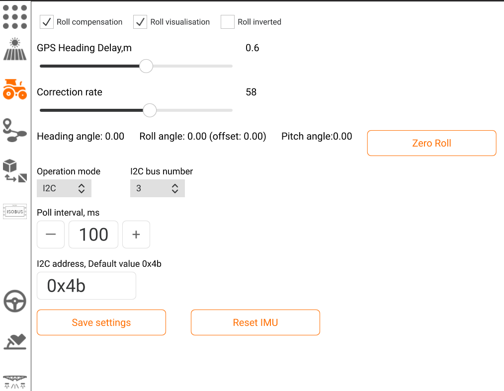
First of all select operation mode (I2C or UART RVC) and communication interface. If you follow wiring scheme described in this section select I2C bus 3 for regular mode and ttyAMA2 interface for RVC mode. Fill in i2c address of your BNO085 IMU - the default address is 0x4b. Sensor poll interval should be a bit higher then GPS navigation solution rate. If your GPS sends position updates at 20Hz frequency set this interval to 40-50.
Roll compensation - check this option to switch on the terrain slopes compensation
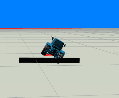
Roll visualisation - tractor model at 3D World will tilt according to real roll angles data from the sensor.
Roll inverted. By default negative angle values are regarded as left roll, positive as right roll. Check this option If in your installation left roll has positive angle values
IMU-GPS fusion settings
As mentioned above the final heading is received by fusing the heading data from GPS and IMU.
Fusing settings are represented by "GPS Heading delay" and "Correction rate" settings.
GPS heading delay is the distance between some previous point and current point. GPS heading is calculated each time this distance is reached.
Zero Roll. Click this button to compensate the roll angle error.